Design of comprehensive wiring scheme for a large scale Park
更新时间:2017-12-31 14:57:00•点击:158783 • Structure Cabling
[guidance] comprehensive wiring is the central nervous system of intelligent building. It uses high quality standard cable and related connection hardware to make up a standard, flexible and open information transmission channel in the building.
The world has entered the information age. With the rapid development of information processing system, the requirements for the rapid, convenient, safe and stable reliability of information transmission are becoming higher and higher. Intelligent building is the product of the information age.
The integrated wiring is the central nervous system of the intelligent building. It uses high quality standard cable and related connection hardware to make up a standard, flexible and open information transmission channel in the building. It can not only transmit voice, data and image inside the building, but also connect to the communication network outside the building. The network network device, different host, terminal, PC and the external equipment to adapt to, can form a flexible topology, sufficient system capacity expansion, through foreign and national public data network (CHINAPAC), integrated services digital network (ISDN) is connected with the domestic and foreign news agencies, information center, information to access the full range of multi channel system.
The integrated wiring system in the design of the park should be equipped with the following features:
Transparency: it can support all current standards, such as telephone communications, data transmission and video applications (IEEE, ITU-T, ANSI, etc.).
Adaptability: there is room for future technology development, such as office automation and satellite high speed network applications.
Flexibility: because the generic cabling system adopts a unified wiring network, that is, a unified transmission medium (twisted pair and optical fiber) to support all types of communication systems, so that users can easily change the location of terminal devices or install new terminal devices.
Summary
The park used to meet the five standard ISO/IEC11801 ultra Taiwan Canbo integrated wiring system as the transmission media voice, data and image communication system in the building, using standard network construction and INTERNET access, data / voice / video "triple play application development mode"; the network operating system and platform coexistence mode considering that, the modern office environment of communication automation (CA), office automation (OA) information transmission system needs a high degree of flexibility and reliability and comprehensive wiring, and easy development and convenient maintenance and management and future expansion.
1. design requirements
(1) the park integrated wiring system is an open architecture, which can support voice and multiple computer data and image transmission systems. It supports a variety of network systems, including Gigabit Ethernet and asynchronous transmission mode (ATM).
(2) included in the integrated wiring system: telephone communication system wiring; computer network system wiring; and can be connected to the external public network.
(3) meet the requirements of computer network system such as office automation of building.
(4) the comprehensive wiring system adopts the full modular structure to facilitate the expansion of the system, and it has great flexibility. When the system changes or the equipment shifts, there is no need to rewire, only the corresponding line jumpers can be jumper.
(5) the wiring system of this project is a tree shaped structure to support the application of various networks in the future and in the future. Interconnect with different network devices through a jumper line. Networks of various logical topological structures can be implemented.
2. design goal
The design of this cabling system aims at building a comprehensive cabling system with openness, flexibility, practicability, expansibility, economy and safety, which integrates voice, communication, data and communication, and achieves the following objectives.
Standardized network systems, various design specifications, technical indicators and products are all in line with international and industrial standards, and can provide multiple brand product support capabilities.
The expansion of the system is combined with the trend of technology development, and the implementation of the wiring scheme is selected, considering the needs at this stage, and it has enough expansion capacity for future development.
Information exchange resources sharing, interconnection through the network, the sharing of resources and the connection with the external network.
3. system characteristics
The system of each floor in the park should be comprehensive, and the user should not rewire when reconnecting or arranging the terminal of the workstation. The network system design must meet the networking requirements of the workstation and meet the requirements of the software operation. The wiring system must be integrated with the network system.
Flexibility: any information point can connect different types of devices, such as computers, printers, terminals or telephones, fax machines and various sensors, image monitoring devices, etc.
Modularization: all connectors should be the standard parts of the block type, convenient to use management and expansion.
Extensibility: taking full account of development and change. When environment change and network equipment upgrade, only need to have flexible jumpers on the distribution rack without rewiring.
Economy: to reduce the cost as much as possible and have good return on investment.
design basis
The scheme design and selected wiring system of this tender follow and conform to the following international standards and specifications, including:
General wiring standard for user building ISO/IEC11801
Commercial building wiring standard EIA/TIA568A
Standard EIA /TIA586 for civil building cable
Ethernet 10 Base-T standard IEEE802.3
Ethernet 100Base-T standard IEEE802.3u
Gigabit Ethernet standard IEEE802.3Z
"Code for electrical design for civil buildings" JGJ/T16--92
"Intelligent building design standard" GB/T 50314-2000
Building communication integrated wiring system YD/T926
Code for electrical design of civil buildings JGJ/T1692
design scheme
The basic structure of integrated wiring system is the Star Park, in accordance with the provisions of the international standard ISO11801, consisting of a work area subsystem, horizontal subsystem, building backbone subsystem, building integrated wiring system subsystem, equipment room subsystem and management subsystem.
The design includes the information points of voice and data, and 4781 information points (including data points and voice points) are designed in the whole park.
1. setting of information points
Information point total see Table 1
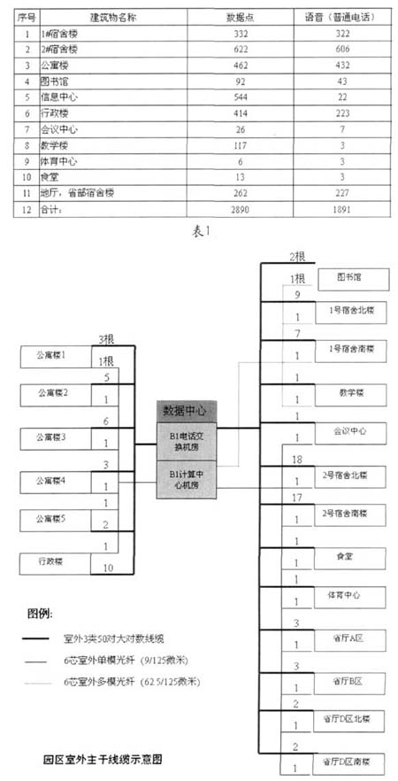
The setting of the 2. subsystem
According to the requirements of the standard, six subsystems are set up.
The work area subsystem, composed of five information module and single port, dual panel; level subsystem is composed of over five 4 UTP double strand; management system, mainly by the five super 24 cabinet type RJ45 port distribution frame, composed of jumper wire frame, 110 type of frame 100 and 24 machine cabinet type optical fiber distribution box; vertical system, mainly by the indoor six core multimode optical fiber and three kinds of 50 pairs of copper; equipment subsystem, mainly by the five super 24 cabinet type RJ45 port distribution frame, composed of jumper wire frame, 110 type 100 and 24 on the frame in the cabinet type optical fiber distribution box; subsystem consists of 110 buildings, 100 of the 19 inch rack frame and 24 cabinet type optical fiber distribution box, six core, six core single-mode fiber optic cable outdoor multimode cable and outdoor three 50 pairs of copper.
The following sub systems are explained in combination with the specific application products.
(1) data center
The main wiring room of the premises distribution system (building cluster network total equipment room) is located at the underground computer network control center of the data center, and the telephone exchange main room (the building group communication total distribution rack) is located in the communication center between the data center and the underground one level.
The data center's underground one, 1, 2, 3 floors all set up the floor distribution line, the underground one floor storey line manages the information point of the underground one and the underground two level, and the other floor distribution line manages the information point of this layer.
From the ground floor, the telephone switchboard room to the first floor, the 1 storey and the 2 floor storey wiring room are laid out 1 indoor 3 types, 50 pairs of cables, from the underground computer network control center to the 1, 2, 3 storey wiring between the laying of 1 indoor 6 core multi-mode optical cable.
(2) library
The information points of the whole library are managed between the 2 layers.
(3) teaching building
The 1, 2 and 3 layers are all set up to manage the information points of the floor. The 1 floor of the teaching building is equipped with the cabinet to connect 1 outdoor 50 pairs of cables pulled by the data center, and then 3 indoor 50 Indoor cables, 1 indoor, 2 floors, 3 storey wiring rooms, each indoor 50 pairs of cables. There are 1 outdoor six core multi-mode optical cables pulled by the data center between the 1 floor storages, and then an indoor six core multi-mode optical cable is drawn from the 2 floor to the 3 floor wiring.
(4) Conference Center
The ground floor is set up to manage the B1 and 1 layer information points between the distribution lines.
(5) canteen
One layer is set up to manage 16 information points of the canteen.
(6) Sports Center
Set up a distribution line to manage the 9 information points of the sports center.
(7) No. 1 dormitory (South)
The 1 level set up the cabinet to access the 7 outdoor 50 pairs of cables pulled by the data center, and then divided 3 indoor rooms, 50 cables to 6 floor storages, 3 indoor 50 cables to 3 floor storey wiring rooms, 1 indoor 50 to the cable layer to the floor level wiring.
There are 1 outdoor six core multi-mode optical cables pulled by the data center between the 1 floor storages, and then an indoor six core multi-mode optical cable is drawn from the 6 floor to the 3 floor wiring. The information between the 3 floor storages is between 2 and 3 levels, 4 levels. The information points between 5 floors and 6 storey 7 floors of the 6 storey wiring rooms, and the information points of the floor between the 1 floors are managed.
(8) No. 1 dormitory building (North Tower)
The 1 level set up the cabinet to access the 9 outdoor 50 pairs of cables pulled by the data center, and then divided 4 indoor rooms, 50 cables to 6 floor storages, 4 indoor 50 cables to 3 floor storey wiring rooms, 1 indoor 50 to the cable layer to the floor level wiring.
There are 1 outdoor six core multi-mode optical cables pulled by the data center between the 1 floor storages, and then an indoor six core multi-mode optical cable is drawn from the 6 floor to the 3 floor wiring. The information between the 3 floor storages is between 2 and 3 levels, 4 levels. The information points between 5 floors and 6 storey 7 floors of the 6 storey wiring rooms, and the information points of the floor between the 1 floors are managed.
(9) No. 2 dormitory (South)
1 to 9 layer is provided in each floor wiring room 17 1 storey outdoor cabinet access from the data center to pull the 50 cable, and then to 2 to 9 every 2 to 50 indoor cable, 1 floor wiring between the access to the data center to pull the 1 outdoor six core single-mode fiber optic cable then, to the 2 to 9 layers of each floor wiring between the indoor six core pulling a multimode fiber optic cable. The information points of this layer are only managed between the distribution lines of each floor.
(10) No. 2 dormitory building (North Tower)
1 to 9 layer is provided in each floor wiring room 18 1 storey outdoor cabinet access from the data center to pull the 50 cable, and then to 2 to 9 every 2 to 50 indoor cable, 1 floor wiring between the access to the data center to pull the 1 outdoor six core single-mode fiber optic cable then, to the 2 to 9 layers of each floor wiring between the indoor six core pulling a multimode fiber optic cable.
(11) administrative building
1 to 5 layer is provided in each floor wiring room 10 1 storey outdoor cabinet access from the data center to pull the 50 cable, and then to the 1 layer 2 layer 3 layer 2 to 50 pull indoor cable to the 4 layer 3 to 50 indoor cable, to the 5 layer 1 the root of 50 indoor cable, 1 floor wiring between the access to the data center to pull the 1 outdoor six core single-mode fiber optic cable, and then to the 2 to 5 layers of each floor wiring between the indoor six core pulling a multimode fiber optic cable. The information points of this layer are only managed between the distribution lines of each floor.
(12) apartment building
There are 5 buildings, apartment buildings, each building cabinet placed in the position of the center area, built in 110 frame and cable distribution frame is used to introduce the data center to pull the 50 cable and single-mode fiber optic cable specific root number in Figure 1 (Park, apartment building 6 unit two, 72 data, 72 voice). Apartment 2 (three units, 6 storey apartment building 3 (108108), 4 units, 6 layer 144144), and 4 apartment buildings (3 units, 5 layer 90, 60, 5 (1) apartment units, 6 48, 48). The wiring is fiber to the building, the twisted pair to the household.